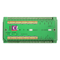
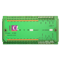
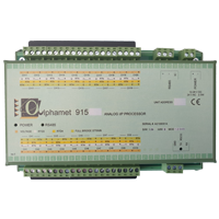
Alpha 614 Strain Gauge Module
€ - POA
Description
What is the Alpha 614 Strain Gauge Module?
The Alpha 614 and 614A provide 16 three-pole channels, which can be used for voltage or current measurement at up to 19 bit resolution and 1uV integrity. Pairs of these channels can be combined to make strain gauge measurements with six poles. Full, Half and quarter bridge strain measurements are supported.
The measurement resolution of a 350 bridge with two active gauges can be as high as 0.1uE. Strain energisation is by constant voltage with full remote sensing to eliminate lead and connector resistance errors.
The bridge supply is directly derived from the A-D reference so that the effect of drift in these circuits does no affect measurement accuracy. Initial bridge unbalance can be compensated for. High quality cage clamp two part screw terminals are used for all connections.
The Alpha 614/614A can be programmed to integrate signals to be measured over one or more complete mains cycles (50 – 60 Hz). This allows measurements to reject large levels of mains borne interference super imposed on micro-volt signals.
During a measurement an auto-ranging facility ensures an input channel is measured on the best range to maintain maximum measurement resolution. A choice of measurement conversion resolution and speed is provided.
These features together with a digital filter function and precision hardware design achieve excellent noise performance in strain gauge applications and general voltage measurements.
Measurements, measurement linearisation, measurement processing and communications are concurrent tasks for optimum performance. Calibration is performed by applying reference inputs and issuing commands to the module. No internal access is required.
As with most other modules in the Alpha series a local serial interface can be used to program and monitor operation locally independent of the communications on the RS485 network.
This can be very convenient during installation or used later to diagnose application problems at the measurement site. Alternatively, it could be used with a permanent local delay. Customized display output can be provided.
LOCAL OUTPUT FACILITIES (614A)
The 614A can be used with an auxiliary output termination panel. This connects to the 914 with a 10-way ribbon connector.
A number of digital outputs and digital inputs can be provided on this panel. These can be controlled directly using commands sent on either serial interface.
Alternatively the standard firmware can be configured to utilize this auxiliary I/O in a particular way for an application.
Such a function can run independently of any communications from a host computer. For example they could be used to drive a local status panel, or provide synchronization to external equipment or events.
Features
- Strain, Voltage and Current inputs in compact DIN rail module.
- Up to 16 Voltage or 8 Strain channels.
- 13 to 19 bit resolution.
- 200 to 10 measurements per second.
- Programmable Measurement Types.
- Full, half and quarter strain bridge support.
- 120R to 1000R Gauges.
- Auxiliary I/O expansion (614A option).
- Scaling, alarm levels, filter functions.
- Second local diagnostic serial interface.
- High speed communications.
Specifications
Interference Rejection
Number of channels / module: 16
Number of 6 pole channels: Up to 8
Connector type input channel: 2 part screw terminal high quality cage clamp.
Number of 3 pole channels: Up to 16
Measurement modes: Voltages – uV DC, mV DC, 4-20mA, ¼ bridge strain, ½ bridge strain, Full bridge strain.
AC Common mode rejection ratio channel group: <0.1uV/V
AC Single channel common mode rejection ratio: <1uV/V
DC channel common mode rejection ratio: <5uv/V
AC series mode rejection ratio 50 to 60 Hz +/- 0.06%: <1uv/V
(Applies to 17,18,19 bit measurements)
Maximum voltages operating:
Max. voltage between any (+) and (-) inputs: 12V
Max. voltage between any two (-) input terminals: 11V
Maximum voltage between any two terminals: 22V
A-D Converter
Overload Protection
5 Measurement resolutions are supported:
19 bits at 10 measurements/s
18 bits at 20 measurements/s
17 bits at 40 measurements/s
15 bits at 100 measurements/s
13 bits at 200 measurements/s
In addition a channel filter function can be applied to any channel.
Channel overload protection:
Passive
50V Continuous
150V for short periods
Voltage Measurement
Auxiliary Channel Expansion (614A)
Input voltage ranges: +10V to -10V, +1.5V to -1.5V, +180mV to – 180mV, +23mV to – 23mV
Automatic range selection is supported.
DC measurement accuracy: +/- 0.015% of reading + 0.01% of range + 6uV
Temperature coefficients DC voltage: 25ppm rdg + 0.1uV/°C
Measurement sensitivity: -23mV range at 18bits
Note: Displayed sensitivity depends on reporting format.
Additional error at 200/sec mode of 0.05% of range.
Connector type: 10 way IDC
Compatible termination panels: Contact supplier
Power Requirement
Connector: 2-Pole screw terminal
Voltage: 24V AC I, 12 to 28V
DC Current: 200mA at 12V, 120mA to 24V
Accuracy:
350R Full: 0.05% rdg + 3uE
350R Half: 0.05% rdg + 5uE
120R Full: 0.05% rdg + 6uE
120R Half: 0.05% rdg + 5uE
Measurement repeatability 24Hrs: 2uE
Sensitivity:
350R Half, Full, 120R Half
0-7000uE: 0.1uE
7000-12000uE: 0.08uE
120R Full Bridge
0-10000uE: 0.2uE
General
RS485 Interface: See Manual, Baud rates to 153KB
Local series interface: RX TX 0 to 5V levels Compatible with most RS232 peripherals.
Status LED’s: 2
Function: Power / Fault comms
Size: 180 * 100 * 40mm
Weight: 400g
Mounting: DIN rail, Stackable
Operating Temperature Range: -20 to 70°C
Relative Humidity (non-condensing): < 90% 0 to 40°C
Vibration: 3g 0Hz to 400Hz in 3 planes.
Programming storage: Secure flash memory Stated Accuracy’s are at 23 °C
Strain Measurements
Bridge Configurations:
Full >= 350R
Half >= 350R
Full 120R (option)
Half 120R (option)
Quarter External Dummy
Bridge Supply: Voltage remote sensed
Bridge Voltage: 1.7V to 5.0V depending on modes of resistance
Accuracy:
350R Full: 0.05% rdg + 3uE
350R Half: 0.05% rdg + 5uE
120R Full: 0.05% rdg + 6uE
120R Half: 0.05% rdg + 5uE
Measurement repeatability 24Hrs: 2uE
Sensitivity:
350R Half, Full, 120R Half
0-7000uE: 0.1uE
7000-12000uE: 0.08uE
120R Full Bridge
0-10000uE: 0.2uE
Temperature coefficient:
350R Full: 0.0003% rdg / °C
350R Half: 0.003 % rdg + 2uE / °C
120R Full: 0.003% rdg / °C
120R Half: 0.003% rdg + 2uE / °C
(Accuracies are stated for gauge factor 2, 2 active gauges, 18 bit ADC, at 23°C for 1 Yr) All specifications subject to change without notice: correct at time of publication. Issue 5.01 DS914A04 refers to 1.05 firmware.)
Downloads
Alpha Server Brochure: [Brochure]
Alpha OPC Brochure: [OPC Brochure]
Alpha 614 Datasheet: [Datasheet]